


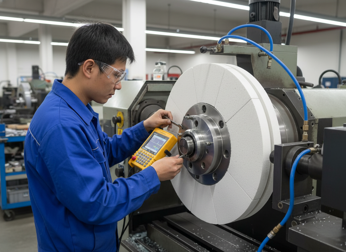
A grinding wheel spinning at 60 m/s that’s off-center by just 2 grams will generate nearly 700 Newtons of radial force. That’s enough to chew through spindle bearings in weeks, leave chatter marks across an entire production run, and turn a precision surface finish into scrap. We’ve seen shops chase “bad coolant” or “wrong grit” for days before someone finally checks the balance. It happens more than you’d think.
Dynamic balancing isn’t glamorous. Nobody’s putting it on a sales brochure. But for high-speed precision grinding, it’s the difference between a process that holds 0.4 μm Ra consistently and one that drifts unpredictably from part to part. This guide walks through what dynamic balancing actually involves, when you need it, and how to do it right based on real shop-floor experience rather than textbook theory.
Why Static Balancing Alone Falls Short at High Speed
Most grinding shops start with static balancing. You put the wheel arbor on a pair of rails, let it settle, and add or remove weight until it doesn’t roll anymore. This corrects mass imbalance in a single plane, and for low-speed applications it’s often sufficient.
But here’s the problem. A grinding wheel is a three-dimensional body. When it spins at 30 to 80 m/s peripheral speed, which is standard for high-speed surface and cylindrical grinding, any mass imbalance creates forces that vary along the wheel’s width. Static balancing can’t see this. It only corrects the net force in one plane, leaving a residual couple unbalance that gets worse as RPM climbs.
This is where dynamic balancing earns its name. It measures and corrects imbalance in two independent planes simultaneously, using either the wheel flanges or a dedicated balance ring. The result is a wheel assembly that runs true at speed, not just on the bench.
I once audited a shop grinding hardened H-13 tool steel with a 400mm diameter wheel at 45 m/s. They’d been static balancing every wheel change and getting acceptable results at first. But after 20 minutes of grinding, vibration would creep up. Turned out the wheel was absorbing coolant unevenly, shifting the balance dynamically. They switched to in-process dynamic balancing and their wheel life jumped by 30%. Same wheel, same grit, same operator. Just better balance control.
Understanding ISO 1940 Balance Quality Grades
Not every application needs the same balance tolerance. ISO 1940-1 defines balance quality grades from G0.4 (the tightest) to G6.3 and beyond, based on the permissible residual unbalance relative to the rotor’s mass and speed. For grinding wheels, the relevant grades typically fall between G1 and G6.3.
The formula for permissible residual unbalance per unit mass is straightforward:
m_per = (G × 1000) / (2π × n/60)
Where G is the balance quality grade in mm/s, and n is the operating speed in RPM. For a wheel running at 3,000 RPM with a G2.5 grade, that works out to roughly 8 grams of permissible residual unbalance per kilogram of wheel mass. Sounds generous until you realize a 20 kg wheel assembly needs to be within 160 grams total, and the centrifugal force from that imbalance still scales with the square of rotational speed.
At higher speeds, even small residual unbalance becomes a serious problem. The centrifugal force relationship is unforgiving: double the speed, quadruple the vibration force from the same amount of unbalance. This is why a wheel that ran fine at 1,500 RPM can destroy a spindle at 4,500 RPM.
| Balance Grade | Typical Application | Permissible Residual Unbalance (at 3,000 RPM, 20 kg wheel) |
|---|---|---|
| G0.4 | Ultra-precision optics grinding | ~2.5 g·mm/kg (very tight) |
| G1 | Precision surface and cylindrical grinding | ~6.4 g·mm/kg |
| G2.5 | General-purpose high-speed grinding | ~16 g·mm/kg |
| G6.3 | Rough grinding, snagging | ~40 g·mm/kg |
For most precision grinding with CBN grinding wheels, targeting G1 or better is the right call. It keeps vibration velocity well under the 0.7 mm/s RMS threshold that ISO 10816 recommends for sensitive machine-tool spindles.
Sources of Imbalance You Might Be Overlooking
Wheel manufacturers do their best to produce consistent products, but some degree of imbalance is inevitable. Here are the most common culprits, roughly in order of how often we see them cause real problems in production:
- Mounting errors. A wheel that’s seated even 0.02 mm off-center on the spindle flange will be imbalanced from the first second. Clean your flanges and spindle taper every single time. No exceptions.
- Density variations in the wheel body. Even within a single manufacturing batch, vitrified bond wheels can have density differences of 1-3% across their cross-section. This is inherent to the pressing and sintering process. Vitrified CBN wheels are more consistent than conventional wheels in this regard, but they’re not immune.
- Uneven wheel wear. As the abrasive surface wears, the mass distribution changes. This is especially problematic with resin bond wheels used for finishing, where the wear pattern can be asymmetric depending on the workpiece geometry.
- Coolant absorption. Vitrified bond wheels are porous by design. If the porosity isn’t uniform, the wheel absorbs coolant unevenly during operation, shifting the balance point. This is a dynamic effect that static balancing on the bench will never catch.
- Flange and adapter wear. Flanges that have been used thousands of times develop microscopic wear patterns. Over time, these create repeatable but incorrect seating positions.
Point number 4 is the one that surprises people. Coolant absorption can shift the balance by 0.5 to 2 grams in the first few minutes of a grinding cycle. That doesn’t sound like much. But on a wheel running at 50 m/s, even a 1-gram shift at 150 mm radius produces roughly 200 N of oscillating radial force. Enough to show up as surface finish degradation on any precision part.
Online vs. Offline Balancing: Choosing the Right System
There are two fundamentally different approaches to dynamic balancing, and the right choice depends on your production volume, tolerance requirements, and how often you change wheels.
Offline balancing uses a dedicated balancing machine or instrumented arbor. You mount the wheel assembly, spin it up, measure the imbalance, and correct it before putting the wheel on the grinder. This works well for shops that pre-assemble wheel sets and run them for extended periods. The equipment cost is moderate, and the process is straightforward.
Online balancing systems are built into the grinding machine itself. Vibration sensors (typically accelerometers mounted on the spindle housing) continuously monitor the vibration signature during operation. When imbalance is detected, the system adjusts correction weights or balance rings automatically, without stopping the machine.
For high-volume production grinding, online systems are worth the investment. They compensate for the dynamic effects that develop during the grinding cycle: coolant absorption, thermal expansion, and progressive wheel wear. A typical online balancer can maintain vibration levels below 0.3 mm/s RMS throughout a shift, compared to 1.0 to 2.5 mm/s for a wheel that was statically balanced before the shift and never touched again.
The correction mechanism in most online systems uses a balance ring with two or more counterweights that can be rotated relative to each other. By positioning the weights at the right angular offset, the system creates an equal and opposite couple to cancel the measured imbalance. Some newer systems use liquid injection into ring cavities, which offers finer correction resolution but adds maintenance overhead.
Matching Wheel Balance to Material and Application
Dynamic balancing requirements aren’t just about speed. The workpiece material and desired surface finish play a significant role in how much balance precision you actually need.
Consider grit size. A coarse wheel running at 36 grit for rough grinding cast iron (using black silicon carbide, grade C) produces surface finishes in the Ra 3.2 to 12.5 μm range. At that roughness level, vibration-induced finish degradation from a slightly imbalanced wheel is masked by the inherent coarseness of the scratch pattern. You still need balance for spindle protection, but the tolerance window is wider.
Now flip to the other end. You’re grinding a carbide insert with a diamond grinding wheel at 280 grit, targeting Ra 0.05 μm. At that resolution, any vibration above about 0.2 mm/s RMS will show up as micro-chatter on the finished surface. The balance requirement here is G0.4 or tighter. There’s no room for “close enough.”
Here’s a practical framework we use when advising customers:
- Rough grinding (Ra 3.2-12.5 μm, grits 16-36#): G6.3 acceptable. Static balancing often sufficient if speed is under 40 m/s. Bond type: metal (M) for aggressive stock removal.
- Medium precision (Ra 0.8-1.6 μm, grits 46-60#): G2.5 target. Dynamic balancing recommended above 35 m/s. Vitrified (V) bond for accuracy, resin (B) for better finish.
- High precision (Ra 0.4-0.8 μm, grits 80-120#): G1 or better. Dynamic balancing mandatory. Online monitoring strongly recommended for production runs.
- Ultra-precision (Ra 0.025-0.4 μm, grits 150-600#): G0.4. Full dynamic balancing with in-process vibration monitoring. Any imbalance shows up immediately at these finish levels.
The material you’re grinding also matters. When grinding hardened tool steels or HSS with aluminum oxide or CBN abrasives, the higher cutting forces generate more vibration feedback through the system. A balanced wheel on a machine grinding soft cast iron might run smoothly, but that same wheel on a hardened D2 steel part could excite a machine resonance. Proper coolant delivery helps manage thermal effects, but it can’t fix a fundamental imbalance problem.
Vibration Monitoring: Your Early Warning System
You can’t manage what you don’t measure. ISO 10816 provides velocity RMS thresholds for different machine classes, and for precision grinding machines with rolling element bearings, the acceptable zone boundary is typically 0.7 mm/s RMS. Below that, the machine is in good shape. Between 0.7 and 1.8 mm/s, you’re in the “alert” zone where something needs attention soon. Above 1.8 mm/s, you should stop and fix it now.
A single-axis accelerometer mounted on the spindle housing near the grinding wheel is the most common setup. For more detailed diagnostics, a triaxial sensor can separate radial vibration from axial and tangential components. But for day-to-day balance monitoring, a single radial measurement is usually enough to catch developing problems before they affect your parts.
One thing that’s often missed: the vibration signature of an imbalanced wheel is a strong 1× rotational frequency component. If you’re seeing 2× or higher harmonics, the problem is more likely misalignment or looseness in the spindle bearings, not wheel imbalance. A simple FFT on the accelerometer output will tell you exactly what’s going on. We’ve seen shops replace perfectly good wheels chasing a 2× vibration problem that turned out to be a worn spindle bearing.
Monitoring vibration over time also reveals when a wheel is developing balance drift. If you see the 1× amplitude trending upward during a shift, it usually means coolant absorption or uneven wear is progressively shifting the mass distribution. That’s the signal to rebalance before the process goes out of spec, not after you find chatter marks on the parts.
Practical Tips for Better Wheel Balance in Your Shop
After years of helping grinding operations optimize their processes, here are the practices that consistently make the biggest difference:
Always mark your wheels and flanges. When you mount a wheel, scribe a reference mark on both the wheel flange and the spindle so you can remount it in the same orientation. If the wheel develops a stable wear pattern, remounting in the same position preserves the balance you’ve already established.
Clean everything before mounting. Coolant residue, swarf, and old adhesive on the spindle taper or flange faces will create an instant imbalance. Use lint-free wipes and a solvent. It takes 30 seconds and prevents hours of troubleshooting later.
Match the wheel to the material correctly before you worry about balance. A hard wheel grinding soft material (or vice versa) creates unpredictable wear patterns that make balance drift worse. For carbon steel, use brown fused aluminum oxide (BFA). For hardened steel and high-speed steel, white fused aluminum oxide (WFA) or CBN. For carbide, diamond or green silicon carbide (GC). For cast iron, black silicon carbide (C). Getting this right first means the wheel wears evenly, and even balance stays stable longer.
Run a vibration check after every wheel change. Don’t wait for the part inspector to flag a problem. A 30-second check with a handheld vibration meter or the machine’s built-in sensor confirms that the new wheel is properly balanced before you start cutting good parts.
Don’t over-tighten the flange bolts. This sounds counterintuitive, but over-torquing can distort the wheel body and actually introduce imbalance. Follow the wheel manufacturer’s torque specifications. If you don’t have them, ask. Reputable suppliers like Zhengzhou Zhongxin provide mounting specifications with their products.
The Bottom Line
Dynamic balancing isn’t optional once you’re grinding above 30 m/s or holding surface finishes tighter than Ra 1.6 μm. The physics are simple: centrifugal force scales with the square of rotational speed, and the tolerance for imbalance scales inversely with the precision of your finish requirement. There’s no workaround, no magic coolant recipe, and no “good enough” wheel that eliminates the need for proper balance.
If your shop is experiencing unexplained vibration, inconsistent surface finish, or accelerated spindle bearing wear, check the wheel balance first. It’s the cheapest diagnostic step and solves more problems than most people expect.
Start with a vibration measurement. If the 1× rotational frequency component exceeds 0.7 mm/s RMS, implement dynamic balancing. If you’re already dynamic balancing and still seeing issues, look at coolant absorption, wheel-to-material matching, and mounting consistency. Work through the list systematically. Most shops can cut their reject rate by 15-25% just by getting wheel balance right.
Need help selecting the right grinding wheel for your application, or want to discuss balance specifications for a new high-speed setup? Zhengzhou Zhongxin Grinding Wheel Co., Ltd. has been manufacturing precision grinding wheels for over two decades and can help you match the wheel specification, bond type, and balance grade to your exact requirements. Reach out at root@shalun.net, call 0371-62513386, or message on WeChat at 15538050608. You can also visit us at 河南省郑州市上街区科学大道1111-1号. Our engineering team can also advise on proper mounting and initial balance procedures for any wheel we supply.