


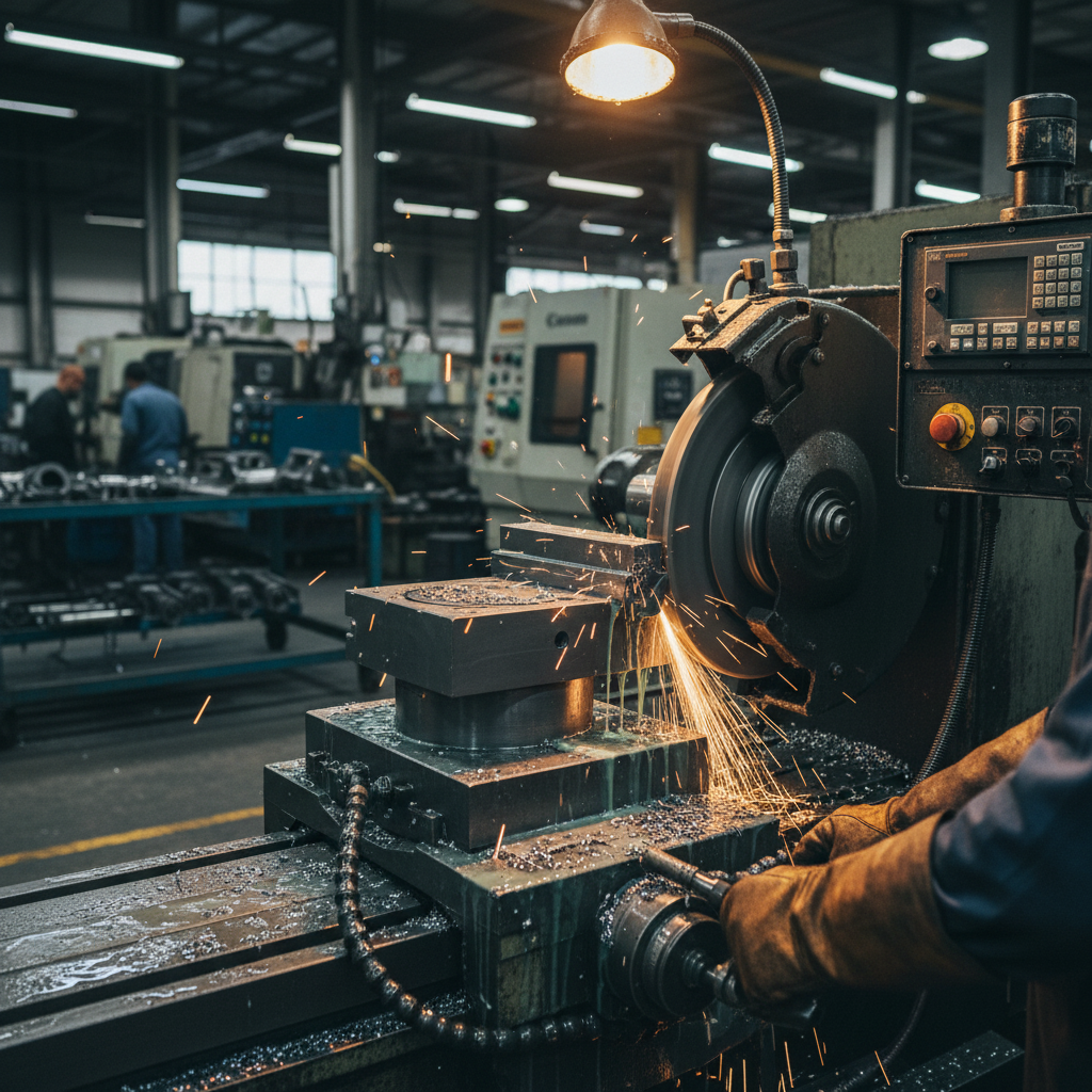
Precision grinding is often the final and most critical stage in high-value manufacturing. When grinding critical components like bearing raceways, gear profiles, or aerospace turbine shafts, surface integrity is non-negotiable. Yet, operators on the shop floor frequently encounter a devastating defect: thermal damage, commonly known as grinding burns. These burns represent more than a cosmetic blemish on a metallic surface. They are structural failures in disguise, capable of reducing the service life of high-precision components by up to 90%. Crucially, the root cause of these thermal defects often traces back to a compromised grinding wheel face, specifically through the phenomena of wheel glazing and loading.
To eliminate these burns, engineers must look beyond simple feed-rate adjustments. While slowing down the cycle time might offer a temporary fix, it destroys productivity. Instead, troubleshooting grinding burns requires a deep understanding of abrasive physics, boundary-layer dynamics, and bond mechanics. This is where open-structure grinding wheels step in. By introducing engineered porosity into the bonded abrasive matrix, manufacturers can fundamentally shift the thermal dynamics of the grinding zone. This technical article explores the physics of grinding burns, diagnoses the crucial differences between wheel glazing and loading, and provides a comprehensive engineering guide on resolving these issues using open-structure wheels coupled with advanced coolant strategies.
Thermal damage destroys parts.
The Physics of Grinding Burns and Part Failure
Grinding is essentially a high-energy micro-machining process. Unlike single-point turning, where a defined tool edge cuts cleanly, grinding relies on thousands of random, geometrically undefined abrasive grains. These grains shear, plow, and rub against the workpiece at extreme linear speeds (often exceeding 30 to 80 meters per second). Each of these interactions consumes energy. The sum of this energy is the Specific Grinding Energy (SGE), which represents the energy required to remove a unit volume of material. A significant portion of this energy is converted directly into thermal energy in the grinding zone.
If the heat generation exceeds the dissipation capacity of the coolant, the temperature in the contact arc spikes. This thermal surge triggers metallurgical changes in the workpiece surface. The primary indicator is surface discoloration, or temper colors. As temperature rises, oxygen reacts with the heated metal, creating an oxide film. A straw-colored surface indicates mild heat, while a deep blue or dark brown oxidation layer points to extreme thermal exposure.
Heat damage in precision manufacturing is a critical defect that cannot be ignored.
Grinding burns cause severe metallurgical damage below the surface:
- Phase Transformations: When grinding hardened steels, if the temperature crosses the austenitizing temperature (approximately 720°C to 800°C for carbon steels) and is rapidly quenched by the coolant, it creates a layer of untempered martensite. This layer, known as the deformed Bielby layer, is extremely hard, brittle, and highly prone to micro-cracking. This deformed layer diminishes fatigue life significantly. Under dynamic loading conditions, this brittle zone acts as a primary site for crack initiation, leading to sudden mechanical component failure.
- Residual Tensile Stresses: Normal, healthy grinding induces compressive residual stresses in the workpiece surface, which resist cracking. Grinding burns, however, cause rapid thermal expansion followed by contraction, leaving behind severe residual tensile stresses. These tensile stresses literally pull the material’s microstructure apart. This shifts the fatigue limit of the material downward, causing premature part degradation under cyclical loads.
- Micro-Cracking & Fatigue Failure: Over time, these tensile stresses and brittle martensitic phases lead to sub-surface micro-cracks. When the component is put into service (such as a bearing rotating at high speeds), the localized stresses concentrate at these cracks. This leads to early spalling, pitting, and catastrophic rolling contact fatigue failure in service.
Diagnosing the Culprits: Wheel Glazing vs. Wheel Loading
Before implementing a technical solution, the operator must accurately identify why the grinding wheel is generating excessive heat. The thermal energy spike is almost always caused by a loss of wheel sharpness. This loss occurs in two distinct ways: glazing or loading. Though both lead to grinding burns, their physical mechanisms are entirely different.
Wheel Glazing occurs when the abrasive grains dull, but the bond holding them is too strong to let them fracture or shed. During a healthy grinding process, as the abrasive grains wear down, the grinding forces on those grains increase. Ideally, these forces should cause the worn grain to fracture (exposing new, sharp micro-edges) or pull out of the bond entirely, a process called self-sharpening. However, if the bond grade is too hard, the dull grains remain locked in place. The tips of the grains wear down into large, flat surfaces known as wear flats. Under light, a glazed wheel face looks highly reflective, shiny, and smooth. The wheel no longer cuts; instead, it rubs. This rubbing action increases friction dramatically, generating massive amounts of heat.
Wheel Loading, on the other hand, occurs when the open spaces (pores) between the abrasive grains become packed with metal chips (swarf). This is especially common when grinding soft, ductile, or highly sticky materials like aluminum, soft steels, and nickel-based superalloys. When the chip clearance space is completely filled, the metal swarf begins to rub directly against the workpiece. This metal-on-metal friction generates extreme heat. The packed metal swarf also physically blocks the grinding coolant from entering the arc of cut, leading to immediate coolant starvation and catastrophic thermal burning. The pores are choked. This is a primary driver of wheel degradation in high-volume production.
To help process engineers quickly distinguish between these two phenomena, the table below outlines their differences, visual indicators, and primary causes:
| Parameter | Wheel Glazing (Dulling) | Wheel Loading (Clogging) |
|---|---|---|
| Physical Mechanism | Abrasive grains wear flat; bond is too hard to allow grain micro-fracture or shedding. | Ductile metal chips (swarf) fill the wheel pores and clog the abrasive face. |
| Visual Appearance | Smooth, glassy, highly reflective surface under shop lights. No metal deposits. | Speckled or solid metallic patches embedded across the grinding wheel face. |
| Workpiece Materials | Hardened steels, high-speed steels (HSS), and hard technical ceramics. | Soft steels, aluminum, brass, titanium, and nickel-based superalloys (Inconel). |
| Frictional Source | Abrasive-on-metal rubbing due to flattened grain tips. | Metal-on-metal rubbing between welded swarf and the workpiece. |
| Primary Causes | Bond grade is too hard; dressing speed or lead is too small; dull dresser. | Insufficient pore volume; low-pressure coolant; sticky/ductile workpiece material. |
The Open-Structure Solution: Engineering High Porosity
When adjustments to the dressing parameters fail to stop glazing or loading, the ultimate solution lies in changing the wheel’s internal architecture. This is accomplished by using open-structure grinding wheels. In bonded abrasives, the structure of a wheel is defined by its structure number (typically ranging from 1 to 16, and sometimes up to 20). A lower structure number indicates a dense wheel with closely packed grains, whereas a high structure number (8 to 16+) denotes an open, highly porous structure.
But why does a high porosity structure solve thermal issues so effectively? The answers lie in the mechanical and thermodynamic benefits of induced, interconnected pores. Choosing open-structure wheels with larger porosity (higher structure number, e.g. 8-16) solves this. It increases coolant intake (acting as micro-pumps), improves chip clearance, and lowers Specific Grinding Energy (SGE) by reducing the actual friction contact area, thus shifting heat away from the part to the chips. This structural modification represents a massive step forward for high-volume automated manufacturing lines.
First, open-structure wheels act as coolant micro-pumps. Traditional dense wheels rely entirely on external coolant spray hitting the grinding zone. Open-structure wheels, however, contain a vast network of interconnected, open pores. As the wheel rotates, these pores absorb coolant like a sponge. When the pore enters the grinding zone, the centrifugal forces and mechanical pressures squeeze the coolant directly into the contact arc. This ensures that the lubricating fluid is present exactly where the abrasive grains touch the metal. By flooding the contact zone from the inside out, the wheel functions as an active heat exchanger, lowering localized temperatures by hundreds of degrees before the structural integrity of the steel is threatened.
Second, the open pores provide massive chip clearance pockets. Instead of metal swarf getting squeezed between the abrasive grain and the workpiece, the ductile metal chips are pushed into the deep pore pockets. The chips remain safely nested in these pockets until the wheel rotates out of the cut, where centrifugal force and coolant nozzles easily flush them away. This completely prevents wheel loading, making it highly effective for grinding notoriously sticky materials like nickel alloys. Without these pocket reserves, swarf builds up in a matter of seconds, leading to localized friction welding, which ruins both the part and the wheel face.
Third, open-structure wheels dramatically reduce the Specific Grinding Energy (SGE). By increasing the spacing between abrasive grains, the active contact area between the grinding wheel and the workpiece is reduced. This reduces unnecessary plowing and rubbing forces. Consequently, the grinding force ratio (the ratio of tangential force to normal force, Ft/Fn) remains stable and highly efficient. When SGE is optimized, less energy is converted into heat, and the heat that is generated is carried away within the metal chips, keeping the workpiece cool. This structural optimization ensures that your grinding forces are utilized for clean shear cuts, rather than wasteful material deformation and heat generation.
For a detailed analysis of balancing these forces, you may read our comprehensive guide on Optimizing Specific Grinding Energy: Using Open-Structure Wheels to Balance Force Ratios.
Breaking the Aerodynamic Air Barrier
Even the best grinding wheel will burn the workpiece if coolant cannot reach the grinding nip. At high operational speeds (wheel speeds v_s > 30 m/s, up to 120 m/s), a fast-rotating grinding wheel acts as an air pump. Because of the viscosity of air, the rotating wheel drags a layer of air along its surface. This creates a high-velocity, high-pressure aerodynamic boundary layer, often called the air barrier. It blocks vital fluid. This fluid blockage leads to massive micro-structural damage.
When a conventional low-pressure coolant nozzle is aimed at the wheel, this high-pressure air barrier acts like an invisible shield. It deflects the coolant away from the grinding zone, creating a phenomenon known as coolant starvation. The grinding zone runs dry, leading to immediate localized grinding burns.
Open-structure grinding wheels help break this air barrier. The irregular, highly porous surface of an open-structure wheel disrupts the smooth laminar airflow, turning it into turbulent, low-pressure micro-currents. However, to completely eliminate the air barrier in demanding industrial environments, mechanical aids must be combined with open-pore wheels.
Mechanical devices such as scraper-boards (deflectors) or aerodynamic baffles are physically positioned very close to the grinding wheel face (typically 0.5 mm to 1.0 mm away). These devices physically cut off the high-speed air current. By blocking the air barrier just before the grinding zone, they create a localized low-pressure pocket. When the coolant is sprayed into this pocket, it hits the grind nip without any wind resistance or deflection. This physical air scraper setup is an absolute necessity when wheel surface speeds exceed 40 meters per second, allowing the coolant stream to hit the contact arc with full kinetic energy.
Air barriers stop coolant.
To deeply understand this fluid dynamics problem, explore our technical breakdown on Breaking the Air Barrier: How Open-Structure Grinding Wheels Prevent Coolant Starvation.
The Coolant Synergy: HPC and Water Chemistry
Successfully running open-structure grinding wheels requires a holistic view of the grinding system. The physical design of the wheel must pair with a reliable fluid delivery strategy. Specifically, engineers must focus on High-Pressure Coolant (HPC) systems and water chemistry.
An HPC system (operating between 50 to 100 bar) is essential for keeping open-structure wheels clean. Because open pores collect metal chips, a low-pressure coolant stream will not have enough kinetic energy to flush the swarf out. An HPC jet, aimed directly at the wheel face outside of the cutting zone, acts as a high-velocity scrubber. It blasts the embedded chips out of the pores, ensuring the wheel face is completely clean before it re-enters the cut. Without high pressure, the porous structure will slowly load and lose its technical advantages.
Besides pressure, water hardness is a critical, yet frequently ignored, parameter. The ideal water hardness for high-pressure grinding applications is 125 to 200 ppm (parts per million). This chemistry must be balanced.
If water hardness is too low (soft water, <125 ppm), the intense agitation from the high-pressure pump (50-100 bar) will cause the grinding coolant to foam excessively. Foam is mostly air. When foam is pumped into the grinding zone, it acts as a thermal insulator, preventing heat from escaping and causing immediate grinding burns. Foam is the enemy of thermal stability.
If water hardness is too high (hard water, >200 ppm), the high temperatures inside the grinding zone will cause calcium and magnesium minerals to precipitate out of the water. These minerals form a hard scale buildup inside the interconnected pores of the open-structure wheel. This mineral buildup quickly plugs the pores, turning your specialized open-structure wheel into a clogged, dense wheel that causes glazing and thermal damage. Thus, water softeners and mineral monitors should be integrated into every centralized coolant filtration loop to maintain a stable, predictable chemistry profile.
Implementation: A Three-Stage Grinding Strategy
To guarantee complete surface integrity and eliminate any residual thermal damage, high-precision operations should adopt a structured, three-stage grinding strategy. This approach manages the material removal rate while systematically removing any micro-deformed layers, such as the Bielby layer.
Stage 1: Roughing. The primary objective here is rapid material removal. This stage utilizes aggressive feed rates and depths of cut. Because of the high material removal rate (MRR), the specific grinding energy is high, and a significant thermal load is generated. This stage inevitably creates a superficial thermally affected layer and introduces high residual tensile stresses. However, by using an open-structure wheel, the depth of this thermally affected layer is kept to an absolute minimum, ensuring that subsequent stages can easily clean it up.
Stage 2: Semi-Finishing. In this intermediate stage, the feed rate and depth of cut are reduced. The primary goal of semi-finishing is to physically grind away the entire thermally affected layer and the residual tensile stresses created during the roughing stage. The depth of cut must be carefully calculated to ensure it penetrates deeper than the damaged heat-affected zone of the previous step, without introducing new thermal damage. Typically, this stage removes 0.02 mm to 0.05 mm of material to clean the metallurgical substrate, providing a perfectly sound foundation for final finishing.
Stage 3: Spark-Out (Finishing). During the final stage, the depth of cut is minimal, and the machine is allowed to spark out (running several passes with zero feed). Spark-out allows the elastic deflection in the machine-tool-workpiece system to relax. It removes the micro-deformed Bielby layer, polishing the surface to its final dimensions. Crucially, this stage relieves any remaining residual stresses, shifting the final surface stress state from harmful tensile stress to beneficial compressive residual stress, which dramatically increases fatigue life. The final surface achieves structural perfection and meets the most demanding aerospace tolerances.
Workpiece Material and Abrasive Matching
No grinding wheel is universal. An open-structure design must be paired with the correct abrasive material to prevent glazing and loading. The following matching rules are vital for optimal grinding performance on various industrial alloys:
- Carbon Steel: Best matched with BFA (Brown Fused Alumina). BFA is tough and highly resistant to fracturing, making it ideal for high-pressure, heavy-duty grinding on materials with relatively low hardness where thermal sensitivity is moderate. This matching ensures rapid and economical material removal.
- Hardened Steel & High-Speed Steel (HSS): Best matched with WFA (White Fused Alumina) or CBN (Cubic Boron Nitride). Hardened steels are highly sensitive to thermal damage. WFA is highly friable (it fractures easily to expose sharp micro-edges), preventing wheel glazing. For high-production runs, CBN is the ultimate superabrasive, maintaining its sharp cutting edges for extended periods. (Note: Never interchange the BFA and WFA abbreviations; they represent completely different abrasive behaviors). WFA self-sharpens perfectly under moderate loads.
- Tungsten Carbide: Best matched with Diamond or GC (Green Silicon Carbide). Carbide is extremely hard and brittle, meaning conventional alumina abrasives will glaze instantly. Diamond, with its unmatched hardness, cuts carbide efficiently, while GC provides a cost-effective alternative for roughing operations. Diamond remains the king of hard metal processing.
- Cast Iron: Best matched with Black SiC (C, Black Silicon Carbide). Cast iron contains free graphite, which can lubricate the cut but also requires a sharp, highly friable crystal-like structure like Black Silicon Carbide to shear the material cleanly without causing loading.
For advanced applications involving brittle, non-metallic materials, you can read our specialized technical article: How to Select Open-Structure Grinding Wheels for Technical Ceramic Grinding.
Summary and Industrial Action Plan
Troubleshooting grinding burns is not a matter of guesswork. It is a systematic process of identifying the thermal bottleneck on the shop floor. When operators face surface discoloration or micro-cracking, they must inspect the wheel face. If the face is glazed, the bond is too hard or the dressing is too fine. If the face is loaded, the chip clearance is insufficient or the coolant pressure is failing to flush the swarf.
Transitioning to open-structure grinding wheels solves both problems simultaneously. By providing engineered pore networks, these wheels facilitate coolant delivery directly to the contact arc, offer safe storage for metal chips, and lower the specific grinding energy. When combined with mechanical scraper-boards to destroy the air barrier, high-pressure coolant, and tightly monitored water hardness, open-structure wheels provide an ironclad defense against thermal damage, protecting both your production rates and the service life of your high-precision parts. Proper selection guarantees success.
Partner with the Precision Experts
For decades, Zhengzhou Zhongxin Grinding Wheel Co., Ltd. has been at the forefront of manufacturing advanced bonded abrasives. We specialize in designing and customizing highly engineered, open-structure grinding wheels tailored to your specific workpiece materials and machining parameters. Whether you are grinding high-performance aerospace alloys, precision bearing raceways, or technical ceramics, our technical engineers can formulate the ideal combination of grain friability, bond grade, and porosity structure to eliminate grinding burns and optimize your production efficiency.
Reach out to our engineering team today for a comprehensive technical consultation or to request custom samples:
Zhengzhou Zhongxin Grinding Wheel Co., Ltd.
Address: No. 1111-1, Kexue Avenue, Shangjie District, Zhengzhou, Henan, China.
Phone / WhatsApp: +86 15538050608
Email: root@shalun.net