

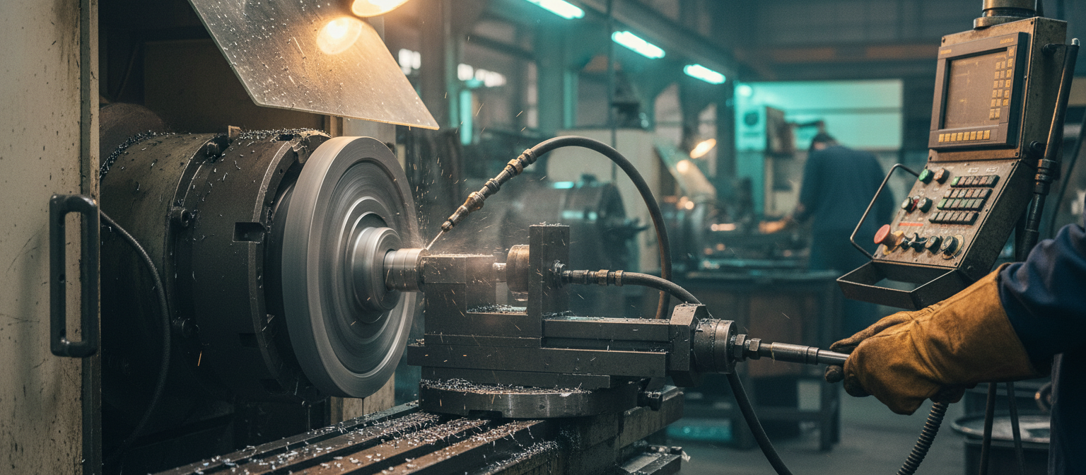
Grinding ductile non-ferrous metals like aluminum presents severe technical challenges that differ fundamentally from grinding high-strength steels or hard alloys. Aluminum is characterized by its high ductility, low hardness, and a relatively low melting point of approximately 660 degrees Celsius. During the grinding process, the extreme shear strains and localized friction at the tool-workpiece interface produce immense thermal energy. Because aluminum is highly prone to plastic deformation under mechanical loads, the metal chips can easily become plasticized. These hot, soft chips fuse directly onto the abrasive grains and embed themselves deep into the pores of the grinding wheel. This physical clogging is technically termed wheel loading. Once wheel loading begins, the exposed abrasive cutting edges lose their sharpness, converting the active cutting action into pure friction. This friction generates rapid heat spikes, resulting in poor workpiece surface finish, dimensional errors, thermal damage, and potential work hardening. To avoid these issues, operators must utilize a dual-action system: applying an open-structure grinding wheel with adequate chip clearance and ensuring optimal coolant penetration into the active grinding zone. For deep technical insights on preventing this loading issue, refer to the detailed guide on Grinding Aluminum and Soft Non-Ferrous Metals Without Wheel Loading.
The Aerodynamic Boundary Layer and the Physics of Coolant Starvation
Even when a machine tool is equipped with a high-flow coolant pump, the actual grinding zone can remain virtually dry. This phenomenon is known as coolant starvation, and its root cause is aerodynamic in nature. When a grinding wheel rotates at standard operational speeds of 30 m/s or higher, its rough, porous peripheral surface acts as a centrifugal fan. This high-speed rotation drags the surrounding air along, creating a turbulent boundary layer of air that wraps tightly around the outer diameter of the wheel. This boundary layer creates a high-pressure air barrier directly in front of the grinding contact arc. Low-pressure coolant jets supplied by standard nozzles lack the kinetic energy and momentum required to penetrate this dense air envelope. Instead, the coolant is deflected away from the contact point, leaving the actual grinding zone without lubrication or cooling. To understand this physical barrier and how to break it, engineers can examine the technical analysis in Breaking the Air Barrier: How Open-Structure Grinding Wheels Prevent Coolant Starvation.
The thickness of the aerodynamic boundary layer increases with the grinding wheel’s diameter and rotational speed. As the peripheral speed reaches 30 m/s, the boundary layer generates a localized tangential air pressure that acts as a physical shield. Conventional coolant delivery systems, which rely on low-pressure flood coolant (typically less than 0.2 MPa), cannot break through this barrier. The coolant jet is diverted, leading to immediate thermal spike and subsequent wheel loading. To resolve this, a mechanical barrier is required to disrupt the boundary layer and establish a safe zone for coolant penetration.
Aerodynamic Baffles: Operating Principles and Performance Data
To disrupt this air envelope, mechanical intervention is highly effective. An aerodynamic baffle, also known as a scraper board, is a physical plate positioned close to the spinning wheel’s surface. This plate physically blocks and redirects the boundary layer of air, preventing it from reaching the coolant entry zone. By stopping the air flow, the baffle creates a localized low-pressure pocket immediately behind the scraper. Experimental studies demonstrate that installing an aerodynamic baffle can reduce the tangential air pressure on the wheel’s face by 64.5% to 74.5% at peripheral wheel speeds of 30 m/s. This significant pressure reduction allows even low-pressure or moderate-pressure coolant jets to enter the grinding zone without deflection, ensuring constant wetting of both the abrasive surface and the workpiece material.
By installing the baffle directly upstream of the coolant nozzle, the high-pressure air envelope is sheared away from the wheel surface. The airflow is forced to divert around the sides of the baffle plate. In the low-pressure wake zone created immediately behind the baffle, the coolant jet can travel through a relatively calm environment, retaining its initial kinetic energy. Consequently, the coolant can easily coat the abrasive surface and penetrate the contact zone. This setup reduces the required coolant delivery pressure while increasing the volumetric flow rate that actually reaches the contact arc, leading to a massive drop in grinding zone temperatures.
Designing Safety-Compliant Baffles: Materials and Clearances
Designing a baffle system for aluminum grinding requires strict adherence to physical and material safety constraints. Since aluminum grinding produces fine particulate dust that is highly flammable and potentially explosive under specific atmospheric concentrations, sparking must be prevented. Baffles must never be constructed of bare carbon steel or other sparking ferrous materials. If the grinding wheel accidentally contacts a steel baffle during high-speed rotation, it will generate a stream of high-temperature sparks, posing an immediate fire hazard. Instead, safe baffle materials include low-friction polymers like Teflon (PTFE), dense Polyoxymethylene (POM/Delrin), or high-performance composite liners. Some systems utilize steel backing plates lined with a thick, sacrificial layer of these polymers. In the event of an accidental collision or wheel thermal expansion, the wheel will safely machine away the soft polymer without generating sparks or damaging the abrasive matrix.
In addition to material selection, physical dimensions and adjustability are critical. The optimal radial gap distance between the baffle’s face and the grinding wheel’s periphery is between 1.5 mm and 3.0 mm. If the gap is wider than 3.0 mm, the air-scraping efficiency drops significantly, allowing too much air to pass through and re-establish the boundary layer. If the gap is tighter than 1.5 mm, the risk of physical collision increases during high-speed operation due to wheel expansion or spindle vibration. Because grinding wheels undergo continuous wear and periodic dressing, their outer diameter decreases over time. Therefore, the baffle must be mounted on a rigid, highly adjustable bracket. This bracket should feature precision adjustment slots or micrometer-style slide mounts, allowing operators to easily adjust the baffle position to maintain the ideal 1.5 mm to 3.0 mm gap after every dressing cycle. The mechanical bracket must be rigid to resist the strong aerodynamic drag forces generated by the high-speed air boundary layer.
The Synergy of Baffles and Open-Structure Silicon Carbide Wheels
While the aerodynamic baffle successfully resolves the coolant delivery problem, the grinding wheel itself must be designed to process ductile materials. Standard, high-density grinding wheels fail quickly on aluminum even with perfect coolant flow, as the small pores cannot store the long, ductile chips. Therefore, engineers must pair the aerodynamic baffle with an open-structure grinding wheel. The open-structure design features large, interconnected pores that act as built-in reservoirs. These pores absorb the coolant delivered by the baffle and transport it directly into the grinding contact zone. During cutting, the pores provide the necessary volume to house the aluminum chips without compacting them. Once the pores rotate out of the contact zone, the centrifugal force and the external coolant flush the chips out, keeping the wheel clean. If loading or glazing does occur due to improper parameter selection, operators can consult the guide on Troubleshooting Grinding Burns: Fixing Glazing with Open-Structure Grinding Wheels for systematic troubleshooting steps.
The optimal wheel specification for this application is a Green Silicon Carbide (GC) wheel with a vitrified bond. Silicon carbide grains are extremely sharp and friable. The high friability ensures that when a grain becomes dull, it easily fractures under the grinding forces, exposing a fresh, sharp cutting edge. This self-sharpening action is critical for grinding soft, non-ferrous metals like aluminum, as it minimizes heat generation and prevents plastic deformation. The vitrified bond is highly stable and does not degrade in the presence of water-based or oil-based coolants. A highly recommended wheel specification is GC80 I/J 12 V. In this specification, GC represents Green Silicon Carbide, 80 indicates a medium-fine grit size that balances surface finish and material removal rate, I or J indicates a relatively soft grade of hardness, 12 represents the structure number (indicating a highly open, porous structure with induced porosity), and V denotes the vitrified bond system.
The combination of Green Silicon Carbide, a soft vitrified bond, and a high structure number (12) provides the ultimate self-sharpening characteristics required for aluminum. As the sharp GC grains slice through the ductile aluminum, they experience low cutting resistance. If a grain does begin to load or dull, the soft bond (I or J grade) allows it to release cleanly, ensuring that fresh, sharp grains are always engaged. The open-pore structure 12 provides a massive void volume. Under the low-pressure wake zone created by the aerodynamic baffle, these open pores act as micro-pumps, drawing in the coolant and delivering it directly to the interface. This synergy eliminates the thermal conditions that cause aluminum to plasticize and stick, maintaining a highly stable grinding process.
Coolant Fluid Speed Matching and Nozzle Dynamics
For maximum cooling efficiency, the fluid dynamics of the coolant delivery system must be matched with the wheel speed. The coolant jet speed (v_j) must match or exceed the peripheral speed of the grinding wheel (v_s). When the wheel speed is 30 m/s, the coolant should be discharged from a coherent jet nozzle at a velocity of at least 30 m/s. Coherent jet nozzles are designed with a convergent internal profile that minimizes turbulence within the fluid stream, producing a solid, highly laminar jet of coolant. This coherent jet retains its shape and velocity over a longer distance, allowing it to easily penetrate any residual boundary layer air that bypasses the aerodynamic baffle. If the jet speed is slower than the wheel line speed, the wheel surface will act as a solid wall, deflecting the fluid and preventing it from entering the grinding arc.
To calculate the required nozzle pressure to achieve the target jet velocity, operators can apply Bernoulli’s equation. For water-based coolants with a density close to 1000 kg/m³, a jet speed of 30 m/s requires a nozzle discharge pressure of approximately 0.45 MPa (4.5 bar). Ensuring that the pump is rated for this pressure and flow rate is essential. Combined with the 64.5% to 74.5% air pressure reduction provided by the Teflon or POM aerodynamic baffle, this matched jet speed ensures 100% coolant penetration, effectively eliminating wheel loading and grinding burns.
Technical Specifications and Material Options Guide
The following technical table provides a complete guide to selecting and setting up an integrated aerodynamic baffle and open-structure wheel system for aluminum grinding operations. It highlights the safety risks, clearance requirements, and optimal grinding wheel specifications.
| Parameter / Component | Technical Specification | Engineering Function & Impact | Safety & Performance Risks |
|---|---|---|---|
| Baffle Material Options | Teflon (PTFE), POM (Delrin), or Polymer-lined composites | Prevents sparking during accidental contact; protects abrasive structure | DO NOT use bare steel or brass. High risk of sparks and explosive dust ignition. |
| Radial Gap Distance | 1.5 mm to 3.0 mm (Optimal: 2.0 mm) | Disrupts air boundary layer; reduces tangential pressure by 64.5% to 74.5% | Gaps > 3.0 mm allow air barrier recovery. Gaps < 1.5 mm risk high-speed wheel collision. |
| Grinding Wheel Specification | GC80 I/J 12 V (Green Silicon Carbide, Vitrified) | Sharp, friable grains with open pores (Structure 12) for chip storage and flushing | Dense wheels (Structure < 8) load instantly; hard bonds cause glazing and burning. |
| Coolant Jet Speed (v_j) | Must match or exceed wheel line speed (v_j ≥ v_s, e.g., ≥ 30 m/s) | Penetrates remaining air barrier; provides maximum heat transfer and lubrication | Low-speed jets are deflected by centrifugal force, leading to coolant starvation. |
| Nozzle Design | Coherent Jet Nozzle (Convergent internal geometry) | Maintains laminar fluid stream; prevents jet dispersion and turbulence | Standard flat or round nozzles disperse quickly, reducing impact momentum. |
| Target Delivery Pressure | ≥ 0.45 MPa (4.5 bar) for 30 m/s operation | Generates the required kinetic energy to match high-speed wheel movement | Low-pressure pumps (< 0.2 MPa) fail to penetrate the contact arc. |
Process Maintenance and Operational Checklist
Implementing this high-performance system requires a structured operational checklist to maintain consistency and safety. Because both the grinding wheel and the baffle are subject to changes during production, operators should follow these guidelines:
- First, check the radial gap daily. As the Green Silicon Carbide grinding wheel is dressed with a diamond tool, its outer diameter is reduced. The operator must loosen the adjustable bracket and slide the aerodynamic baffle forward to maintain the 1.5 mm to 3.0 mm gap. Ensure that all locking bolts are fully tightened to prevent vibration-induced movement during grinding.
- Second, inspect the polymer scraper edge. Over time, high-speed air currents and stray abrasive particles can erode the Teflon or POM surface. If the scraper edge shows signs of deep grooves or embedded metal particles, it should be trimmed or replaced. Embedded aluminum particles can act as a friction source, generating unwanted heat or scratching the wheel face.
- Third, verify the coolant filtration system. Open-structure grinding wheels rely on clean coolant to flush chips out of the large pores. If the coolant contains recirculated aluminum swarf, these particles will get trapped in the open pores, causing premature wheel loading. A paper band filter or magnetic separator capable of filtering particles down to 5 microns is highly recommended for aluminum grinding operations.
Conclusion and B2B Manufacturing Support
Combining aerodynamic baffles and open-structure Green Silicon Carbide grinding wheels represents a highly effective approach to aluminum grinding. By reducing the tangential air pressure by up to 74.5% and utilizing a highly porous wheel matrix, this setup overcomes coolant starvation and wheel loading. This system enables manufacturers to achieve higher material removal rates, excellent surface finish, and longer wheel life while eliminating the risk of grinding burns and workpiece distortion.
For high-volume industrial grinding operations, selecting the right wheel grade and structural setup is vital. Zhengzhou Zhongxin Grinding Wheel Co., Ltd. specializes in manufacturing premium vitrified and resinoid bonded grinding wheels designed specifically for non-ferrous metals and precision engineering applications. Our engineering team can customize open-structure Green Silicon Carbide wheels (such as GC80 I/J 12 V and other specialized pore volumes) to match your specific production parameters and baffle designs.
For technical inquiries, product specifications, or to request a quote, contact our engineering and support division:
Company: Zhengzhou Zhongxin Grinding Wheel Co., Ltd.
Email: root@shalun.net
Phone/WhatsApp: +86 15538050608
Address: No. 1111-1, Kexue Avenue, Shangjie District, Zhengzhou, Henan, China (河南省郑州市上街区科学大道1111-1号)