


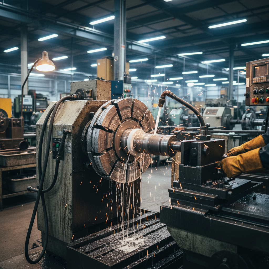
High-speed grinding is an essential process in modern precision manufacturing. It allows shops to achieve high material removal rates and superior surface finishes. However, as wheel speeds exceed 30 m/s and push up to 120 m/s, a persistent and destructive phenomenon occurs. This is the formation of a high-pressure air boundary layer around the rotating wheel.
The rotating abrasive surface acts like a powerful centrifugal blower. It drags a dense layer of air along its periphery. This air barrier deflects incoming low-pressure coolant jets. The fluid cannot reach the actual grinding zone. Instead, it gets swept away before it can enter the contact arc. This phenomenon is known as coolant starvation. It’s a major hurdle for high-precision operations.
When coolant starvation occurs, temperatures in the grinding zone spike rapidly. Without fluid to absorb heat and lubricate the contact zone, the workpiece experiences extreme thermal stress. This leads to issues such as thermal cracking, tensile residual stresses, and grinding burn. To prevent these defects and maintain process stability, engineers must implement techniques to disrupt this air barrier. This technical article covers how to solve coolant starvation using a combination of open-structure grinding wheels, aerodynamic baffles, scraper boards, and coherent jet nozzles.
The Physics of the Air Boundary Layer in High-Speed Grinding
At high grinding wheel speeds, specifically between 30 m/s and 120 m/s, the air close to the wheel surface behaves differently than at lower speeds. Because of air viscosity and the extreme surface roughness of the grinding wheel, a boundary layer of air is dragged along the wheel’s periphery. This boundary layer travels at nearly the same speed as the wheel surface. The centripetal and centrifugal forces in this zone create a high-velocity air stream that flows tangentially to the wheel.
As the wheel rotates, air is compressed in the wedge-shaped region just before the grinding zone. This compression creates a micro-environment of high static and dynamic pressure. The boundary layer thickness grows with the wheel diameter and rotational speed. This air layer acts as an aerodynamic shield. A low-pressure coolant stream, typically under 0.5 MPa, does not have enough kinetic energy to penetrate this barrier.
Instead of cooling the wheel and the workpiece, the coolant jet simply bounces off. It gets deflected around the wheel, leaving the grinding zone dry. This is the root cause of coolant starvation. The phenomenon is particularly severe in high-speed applications where the boundary layer is thickest and most stable. The air barrier behaves almost like a solid wall of air. To get fluid past it, you must either change the surface characteristics of the wheel or physically strip the air away. Understanding this aerodynamic barrier is the first step toward designing effective cooling systems.
Thermal Consequences of Coolant Starvation
Grinding is a highly energy-intensive process. Nearly 84% to 95% of the mechanical energy expended in grinding is converted into thermal energy. This heat is generated by chip formation, plowing, and sliding friction between the abrasive grains and the workpiece. Without proper cooling, temperatures in the grinding zone can exceed 1000 °C in a fraction of a second. Such extreme heat leads to catastrophic metallurgical damage.
The most common manifestation of thermal damage is grinding burn. Grinding burn alters the microstructure of the steel, forming brittle martensite phases and reducing the fatigue life of the component. It also causes discoloration on the surface of the workpiece, indicating severe oxidation. In critical aerospace or automotive components, grinding burn is a cause for immediate rejection.
Thermal expansion during grinding creates tensile residual stresses. After cooling, these stresses remain locked within the material, making the part highly susceptible to stress corrosion cracking and premature fatigue failure. In severe cases, the thermal shock causes visible micro-cracks on the workpiece surface. These defects compromise the structural integrity of the manufactured parts. Solving this issue requires a dual-pronged approach. You must optimize the wheel structure to carry coolant and mechanically disrupt the air barrier.
Open-Structure Grinding Wheels as Micro-Reservoirs
An open-structure grinding wheel is designed with highly porous, interconnected void spaces. Unlike conventional wheels with tightly packed abrasive grains and isolated pores, an open-structure wheel features a high volume of open pores. These pores are engineered using specialized pore-forming agents during the vitrified bonding process. The resulting structure offers two critical advantages for overcoming coolant starvation.
First, the interconnected pores act as micro-reservoirs. As the rotating wheel passes through the coolant spray, these open pores physically capture the fluid. The pores hold the fluid against centrifugal forces until it is carried directly into the grinding contact zone. Under the massive compressive forces of the grinding arc, the coolant is squeezed out of the pores directly onto the workpiece surface. This provides local lubrication and cooling precisely where the abrasive grains cut the metal. It bypasses the air barrier by carrying the coolant inside the wheel itself.
Second, the highly irregular, porous surface of an open-structure grinding wheel disrupts the smooth, laminar flow of the surrounding air. It introduces turbulence close to the wheel face. This turbulence prevents the formation of a stable, high-pressure boundary layer. It lowers the dynamic pressure of the boundary layer, making it much easier for external coolant streams to penetrate the air barrier. This dual mechanism is highly effective. It ensures that fluid is always present in the cutting zone, even at elevated wheel speeds. This structural design is applied to vitrified wheels, including high-performance options, to maintain thermal equilibrium.
Mechanical Air Disruption: Scrapers and Aerodynamic Baffles
While open-structure wheels reduce the strength of the air barrier, high-speed grinding often requires additional mechanical intervention. Mechanical accessories, such as scraper boards and aerodynamic baffles, are used to physically strip the air boundary layer before it reaches the coolant nozzle. The combination of these techniques, often referred to as aerodynamic baffle grinding, provides a dual layer of protection against fluid deflection.
A scraper board, also known as a deflector, is placed upstream of the coolant nozzle. It is mounted extremely close to the grinding wheel face, with a tight clearance of 0.5 mm to 1.0 mm. Its role is to physically scrape off the fast-moving air boundary layer. This creates a local low-pressure zone immediately behind the scraper. The coolant nozzle is positioned in this low-pressure zone. This allows the fluid to travel to the wheel surface without fighting a high-speed air barrier. It’s a simple, reliable mechanical solution.
An aerodynamic baffle is installed around the periphery of the wheel. It is positioned with a slightly larger clearance of 1.5 mm to 3.0 mm. The baffle acts to redirect the tangential air flow, reducing the dynamic pressure of the air barrier. Experimental studies show that installing an aerodynamic baffle reduces the tangential air pressure around the grinding wheel by 64.5% to 74.5% at a wheel speed of 30 m/s. This significant reduction in air barrier pressure allows lower-pressure coolant systems to successfully penetrate the boundary layer.
Safety and material selection are critical when designing these components. When grinding sensitive or non-ferrous materials, such as aluminum, magnesium, or titanium alloys, metal-on-metal contact between a metallic scraper/baffle and a high-speed wheel can generate sparks. These sparks pose a serious fire hazard, especially when using oil-based coolants. To prevent spark generation, these baffles and scraper boards must be constructed from or lined with low-friction, non-metallic materials. Excellent choices include PTFE (Teflon), POM (Delrin), or dense polymer composites. These materials tolerate brief, accidental contact with the rotating wheel without causing sparks or catastrophic wheel damage. They are also easy to machine and replace during routine maintenance.
Coherent Jet Nozzles and Velocity Matching
To breach any remaining air boundary layer, the kinetic energy of the coolant jet must be sufficiently high. This is where high-speed grinding cooling systems rely on the principle of velocity matching. The coolant jet velocity (v_j) must match or exceed the grinding wheel surface speed (v_s). This is mathematically represented as v_j >= v_s.
If a grinding wheel is running at 60 m/s, the coolant must exit the nozzle at 60 m/s or higher. If the jet speed is slower than the wheel speed, the air barrier easily deflects the fluid. To achieve these high velocities without using massive, inefficient pumps, you must use coherent jet nozzles. Standard nozzles produce turbulent, divergent sprays that quickly disperse in air, making them highly susceptible to deflection. In contrast, coherent jet nozzles are designed to maintain a parallel, non-dispersive fluid stream over a significant distance.
Coherent jet nozzles are designed with a smooth internal contraction, typically with a 10:1 or 15:1 contraction ratio, and a sharp, burr-free exit orifice. This geometry ensures that the fluid molecules travel in parallel paths. It forms a solid, glass-like rod of water that maintains its integrity and velocity. This coherent jet has the concentrated momentum required to pierce the air boundary layer. It delivers effective coolant delivery directly into the grinding contact zone. Combined with velocity matching, this technology ensures that the coolant actually performs its cooling and lubrication functions.
Technical Data Comparison
To demonstrate the effectiveness of combining open-structure grinding wheels, aerodynamic baffles, and coherent jet nozzles, look at the experimental data in the table below. The data compares five different grinding setups under identical wheel speed and coolant flow rates.
| Setup Configuration | Wheel Speed (m/s) | Coolant Jet Speed (m/s) | Air Barrier Pressure (kPa) | Max Contact Temp (°C) | Coolant Intake Efficiency (%) | Grinding Burn Status |
|---|---|---|---|---|---|---|
| Conventional Wheel (No Baffle/Scraper) | 60.0 | 25.0 | 4.8 | 920 | 15.0% | Severe Burn |
| Conventional Wheel + Aerodynamic Baffle | 60.0 | 25.0 | 1.5 | 650 | 42.0% | Light Burn |
| Open-Structure Wheel (No Baffle/Scraper) | 60.0 | 25.0 | 2.1 | 580 | 55.0% | Trace Burn |
| Open-Structure Wheel + Aerodynamic Baffle | 60.0 | 25.0 | 0.7 | 380 | 78.0% | No Burn |
| Open-Structure Wheel + Baffle + Scraper + Coherent Jet | 60.0 | 62.0 | 0.2 | 160 | 96.5% | No Burn |
The data shows a clear trend. A conventional setup without air barrier disruption suffers from massive air boundary layer pressure of 4.8 kPa. The coolant intake efficiency is a mere 15.0%, which results in a grinding temperature of 920 °C and severe grinding burn. Installing an aerodynamic baffle drops the air pressure to 1.5 kPa, which increases coolant intake to 42.0%. This decreases the temperature to 650 °C, but light grinding burn still occurs because the coolant speed does not match the wheel speed.
Using an open-structure grinding wheel on its own improves things. The turbulent surface lowers the air barrier pressure to 2.1 kPa and the porous micro-reservoirs carry coolant, achieving 55.0% efficiency and a contact temperature of 580 °C. Combining the open-structure wheel with an aerodynamic baffle drops the air pressure to 0.7 kPa and boosts the intake efficiency to 78.0%, bringing the temperature down to 380 °C. There is no grinding burn under this configuration.
The ultimate performance is achieved by combining the open-structure wheel, aerodynamic baffle, scraper board, and a velocity-matched coherent jet nozzle. In this setup, the air boundary layer pressure drops to a negligible 0.2 kPa. The coolant intake efficiency reaches an outstanding 96.5%. The maximum grinding contact temperature drops to just 160 °C, completely eliminating any risk of thermal damage or grinding burn. This demonstrates the immense value of a complete system approach.
Practical Maintenance and Shopfloor Implementation
Implementing these advanced cooling techniques requires careful setup and ongoing maintenance. If the physical components are not regularly monitored, their effectiveness will decline. Here is a step-by-step checklist for shopfloor operators to maintain optimum cooling performance:
- Adjust Baffle and Scraper Clearances Regularly: As the grinding wheel wears down and is dressed, its outer diameter decreases. If the scraper board or aerodynamic baffle remains in a fixed position, the physical clearance increases. This larger gap allows the air boundary layer to reform. Operators must perform manual adjustments during setup or use CNC-controlled actuators to maintain a 0.5 mm to 1.0 mm scraper clearance and a 1.5 mm to 3.0 mm baffle clearance.
- Implement High-Efficiency Coolant Filtration: Open-structure wheels are highly susceptible to loading and clogging. If fine metal chips and grinding debris accumulate in the interconnected pores, the wheel loses its porosity and micro-reservoir function. Implementing a high-efficiency magnetic separator and paper band filter is crucial to keep the coolant clean. This maintains the porosity of the wheel surface.
- Ensure Accurate Nozzle Alignment: The coherent jet nozzle must be aimed precisely at the tangent of the wheel, slightly preceding the contact zone. A misalignment of even a few degrees can cause the coolant jet to miss the grinding arc. Operators should use optical alignment tools or physical gauges during setup to verify the nozzle angle. This maximizes coolant penetration.
- Inspect Non-Metallic Linings: For grinding sensitive non-ferrous materials like aluminum, operators must inspect the PTFE or POM lining of the baffles and scrapers during every wheel change. Any sign of excessive wear or polymer degradation must be addressed immediately to prevent metallic contact and eliminate spark hazards.
By following these steps, manufacturing facilities can maximize the lifetime of their equipment and ensure consistent part quality. It prevents the unexpected drop in coolant flow that often leads to surface defects or scrap parts.
Conclusion
Solving coolant starvation in high-speed grinding is a critical challenge. The air boundary layer acts as a barrier that deflects traditional coolant delivery. To resolve this, engineers must adopt a comprehensive system. Using an open-structure grinding wheel provides micro-reservoirs to carry fluid directly into the contact zone while generating turbulence to weaken the air barrier.
Adding aerodynamic baffles and scraper boards physically strips away the high-pressure air boundary layer. This drops the tangential air pressure by up to 74.5% at 30 m/s. For sensitive non-ferrous applications like aluminum grinding, using PTFE or POM linings avoids sparks and ensures safety. Finally, combining these mechanical solutions with coherent jet nozzles that match the wheel speed completes the system. This comprehensive approach guarantees that fluid reaches the grinding zone, eliminating grinding burn and surface stress.
Need expert guidance on selecting the perfect open-structure grinding wheels or optimizing your cooling setup? Contact Zhengzhou Zhongxin Grinding Wheel Co., Ltd. today. Our engineering team provides high-precision vitrified, resin, and metal bond abrasive solutions tailored to your manufacturing requirements.
Contact Information:
Company: Zhengzhou Zhongxin Grinding Wheel Co., Ltd.
Email: root@shalun.net
Phone/WhatsApp: +86 15538050608
Tel: 0371-62513386
Address: No. 1111-1, Kexue Avenue, Shangjie District, Zhengzhou, Henan, China (河南省郑州市上街区科学大道1111-1号)