


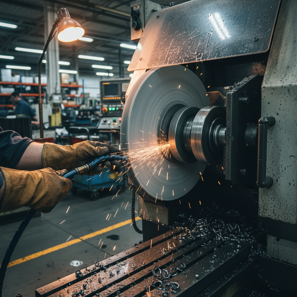
At wheel surface velocities exceeding 30 m/s, and frequently reaching up to 80 to 120 m/s in modern high-productivity cylindrical and profile grinding, the rotational motion of the abrasive body acts as a powerful centrifugal pump. The highly textured surface of the grinding wheel drags the adjacent air along with it. This boundary layer of air rapidly accelerates, matching the wheel line speed at the wheel-workpiece contact zone. As a result, a high-velocity, high-pressure aerodynamic boundary layer forms around the periphery of the grinding wheel. This boundary layer is not a gentle draft; it is a rigid, high-velocity envelope of air that rotates in synchrony with the wheel. At higher surface speeds, this layer becomes increasingly compressed and cohesive. The aerodynamic pressure field peaks immediately ahead of the grinding nip, creating a localized high-pressure zone that acts as a physical shield. Fluid dynamic models show that the velocity profile of this air envelope decreases exponentially with distance from the wheel face, meaning the strongest aerodynamic barrier is concentrated within the first few millimeters of the abrasive surface.
Understanding Coolant Starvation and Thermal Damage
The primary consequence of this aerodynamic boundary layer is coolant starvation. When standard cooling systems deliver fluid at conventional low pressures (typically 2 to 5 bar), the jet lacks the kinetic energy to penetrate this high-velocity air shield. Instead, the oncoming air barrier deflects the fluid jet, forcing the coolant stream away from the wheel surface before it can reach the actual contact zone, also known as the grinding nip or contact arc. Under these conditions, the fluid is swept away before it can perform its vital roles of cooling, flushing, and lubrication.
Without adequate fluid penetration, the grinding zone operates under dry or near-dry conditions. Precision grinding is inherently a high-energy process where almost all mechanical energy converts into heat. In the absence of coolant lubrication and heat removal, temperatures in the contact zone can easily spike above 800°C. This extreme thermal concentration induces critical surface integrity issues. Under these conditions, the workpiece material undergoes localized thermal expansion followed by rapid cooling, leading to tensile residual stresses, thermal burning (grinding burn), and microscopic cracks. Concurrently, the grinding wheel itself experiences accelerated thermal wear, causing premature grain glazing, binder degradation, and premature loss of wheel profile accuracy. This cycle leads to increased reject rates and frequent downtime for wheel dressing.
The Open-Structure Grinding Wheel Solution
To break this air barrier without relying solely on raw mechanical force, engineers use open-structure grinding wheels. These wheels feature a high volume of uniform, interconnected pores designed directly into the abrasive matrix. The highly porous design addresses the boundary layer problem through two distinct physical mechanisms that work in tandem to guarantee fluid delivery.
First, the open pore structure breaks the continuous, flat geometry of the grinding wheel face. This structural discontinuity disrupts the laminar airflow that typically builds up around solid or closed-structure wheels. As the open-pore wheel rotates, the surface voids generate localized turbulence, breaking the laminar boundary layer into smaller, chaotic eddies. This disruption drastically reduces the dynamic pressure of the aerodynamic barrier, weakening its ability to deflect incoming coolant. Instead of confronting a solid aerodynamic wall, the coolant jet meets a turbulent air-pore mixture that has much lower resistance.
Second, the interconnected network of pores acts as an internal transport system. Instead of the coolant slipping off a solid wheel surface, the open pores absorb the fluid before it enters the contact zone. Capillary action draws the coolant deep into the interconnected pore matrix, holding it securely against the deflecting force of the air barrier. As the wheel rotates into the grinding nip, centrifugal force pushes this stored coolant outward, discharging it directly into the contact arc. This mechanism ensures that fluid is present precisely at the interface of the abrasive grain and the workpiece, eliminating the risk of starvation even at elevated wheel speeds. The wheel essentially acts as a localized fluid reservoir that deposits coolant directly inside the grinding nip.
Specific Grinding Energy and Force Ratio Optimization
In precision abrasive machining, Specific Grinding Energy (SGE) represents the total energy required to remove a unit volume of workpiece material. SGE is a vital metric for monitoring grinding efficiency and preventing thermal damage. When a grinding wheel becomes glazed or starved of coolant, SGE rises dramatically. This rise occurs because a significant portion of the energy is wasted on friction and material plowing rather than active chip formation. The energy that should go into shearing material is instead converted into thermal energy, which flows directly into the workpiece.
To monitor and maintain this process, engineers analyze the force ratio (Ft/Fn), where Ft is the tangential grinding force and Fn is the normal grinding force. A higher force ratio indicates sharp, efficient cutting action, where the grains cleanly shear the material. A low force ratio indicates grain dulling and excessive plowing, where the normal force increases disproportionately compared to the cutting force, pushing energy directly into the workpiece as heat. When coolant delivery fails, the lack of lubrication accelerates grain wear, leading to rapid glazing and a sharp decline in the force ratio.
Open-structure grinding wheels play a major role in keeping these metrics balanced. By providing ample chip clearance within the pore spaces, these wheels prevent chip loading and wheel glazing. The abrasive grains maintain their sharp cutting edges, which supports self-sharpening behavior. Consequently, the force ratio remains stable and the overall Specific Grinding Energy is minimized, mitigating the risk of thermal damage. For a detailed discussion on balancing force ratios and optimizing specific grinding energy, see Optimizing Specific Grinding Energy: Using Open-Structure Wheels to Balance Force Ratios.
Integrating Aerodynamic Baffles and Scraper-boards
While changing the wheel structure is highly effective, integrating external aerodynamic controls provides an additional layer of protection against coolant starvation. This is achieved by installing scraper-boards (deflectors) and aerodynamic baffles to physically dismantle the boundary layer before the coolant is applied.
A scraper-board or deflector is a wear-resistant plate mounted immediately upstream of the coolant nozzle. This device is positioned extremely close to the outer diameter of the grinding wheel, with a clearance typically set between 0.5 mm and 1.0 mm. As the wheel rotates, the scraper-board physically shaves off the rotating boundary layer of air. This mechanical stripping action creates a localized low-pressure vacuum zone directly behind the plate. This local low-pressure zone acts as a quiet pocket, shielding the oncoming coolant nozzle from high-velocity air currents.
An aerodynamic baffle is integrated directly with the coolant nozzle block. By blocking the concurrent airflow that circles the wheel, the baffle creates a draft-free pocket. When the coolant nozzle sprays into this low-pressure, draft-free zone, the fluid stream experiences zero aerodynamic deflection. This allows even low-to-medium pressure coolant to reach the grinding zone without being swept away by the air barrier. Combining a mechanical scraper-board with an aerodynamic baffle ensures that the path from the nozzle orifice to the grinding nip remains entirely clear of turbulent air interference.
High-Pressure Coolant (HPC) and Jet Velocity Matching
To achieve complete penetration of the boundary layer, the fluid delivery system must match the kinematics of the grinding wheel. The fundamental kinematic rule for high-pressure coolant (HPC) delivery is that the coolant jet velocity (v_j) must match or exceed the wheel line speed (v_s):
v_j >= v_s
If the jet velocity is lower than the wheel speed, the boundary layer will deflect the coolant. To generate sufficient jet velocity, the coolant system must operate at pressures ranging from 50 to 100 bar. The relationship between nozzle pressure (P, in bar) and jet velocity (v_j, in m/s) for water-based coolant can be calculated using the fluid dynamics formula: v_j ≈ 14 * sqrt(P). For example, to match a wheel line speed of 80 m/s, the system requires a nozzle pressure of approximately 33 bar. Operating at 50 to 100 bar provides a necessary safety margin to overcome the aerodynamic pressure field. To maintain the integrity of this high-velocity stream, the system should use contraction-type Coherent Jet Nozzles. These nozzles prevent the fluid jet from diverging or entraining air, ensuring a solid, high-impact stream of coolant hits the target.
Fluid chemistry and properties are equally critical in high-pressure open-pore grinding. Water hardness must be controlled strictly between 125 ppm and 200 ppm. If water hardness falls below 125 ppm, the fluid becomes highly prone to foaming under high pressure, which introduces air bubbles into the grinding zone and reduces lubricity. Conversely, if water hardness exceeds 200 ppm, mineral scale and calcium deposits can accumulate inside the open pore structure of the wheel. This scaling restricts coolant transport, clogs the capillary channels, and causes premature wheel loading. To learn more about calibrating these fluid parameters, refer to Optimizing Open-Structure Grinding Wheels for High-Pressure Coolant Systems.
Material Matching and Wheel Selection Principles
Selecting the correct open-structure wheel requires matching the wheel hardness and abrasive type to the mechanical properties of the workpiece. The core principle of grinding wheel selection is: hard wheels for soft materials, and soft wheels for hard materials. This counter-intuitive rule is fundamental to preventing thermal damage and maintaining dimensional accuracy.
When grinding soft materials, the abrasive grains do not dull quickly, but the wheel is prone to loading with ductile chips. A harder wheel grade with an open structure holds the grains long enough to utilize their full life while providing deep pores for chip clearance. When grinding hard materials, the abrasive grains dull rapidly due to high mechanical stresses. A softer wheel grade is necessary because it allows the dulled grains to fracture and break away under the grinding forces, exposing new, sharp grains—a process called self-sharpening. If the wheel is too hard, dulled grains will remain in place, causing intense friction, glazing, and catastrophic thermal burn.
The selection of the abrasive grain itself is divided between conventional alumina grains and superabrasives:
- Brown Fused Alumina (BFA): Highly tough and resistant to fracturing, BFA is preferred for grinding high-tensile materials, carbon steels, and tough alloy steels. Its high durability allows the grains to withstand heavy grinding loads without premature breakdown.
- White Fused Alumina (WFA): Highly friable and sharp, WFA fractures easily under stress, exposing new cutting edges. This characteristic makes it ideal for grinding hardened steels, high-speed steels (HSS), and heat-sensitive alloys where maintaining low grinding temperatures is critical. It is essential not to confuse WFA with BFA, as their thermal and structural fracturing behaviors are completely different.
- Superabrasives (CBN and Diamond): For extremely hard materials, cubic boron nitride (CBN) is used for ferrous alloys, while diamond is reserved for non-ferrous metals and ceramics. Open-structure vitrified CBN wheels combine structural stability with excellent pore volume.
For applications involving difficult-to-machine materials, matching the wheel grade and structure is essential. For instance, in carbide centerless grinding, using the correct open-structure setup is necessary to prevent chatter and thermal burn. You can read more about these material-specific strategies in Eliminating Chatter and Burn in Carbide Centerless Grinding: An Open-Structure Wheel Guide.
Comparative Analysis: Conventional vs. Open-Structure Systems
To illustrate the differences between conventional grinding systems and optimized open-structure systems, the table below compares key operational parameters across several metrics:
| Parameter | Conventional Closed-Structure Wheels | Open-Structure Grinding Wheels |
|---|---|---|
| Porosity Volume (%) | 30% to 45% (mostly closed/isolated pores) | 48% to 65% (fully interconnected pores) |
| Boundary Layer Interaction | Promotes laminar air barrier formation | Disrupts airflow, causing localized turbulence |
| Coolant Transport Method | External surface flooding (deflection risk) | Internal capillary absorption & centrifugal delivery |
| Specific Grinding Energy (SGE) | High (due to loading, plowing, and friction) | Low (efficient cutting, minimal plowing) |
| Force Ratio (Ft/Fn) | Unstable (rapidly decreases as wheel glazes) | Stable and high (self-sharpening is maintained) |
| Workpiece Burn Risk | High (due to coolant starvation and friction) | Minimal (sustained fluid supply to contact zone) |
Technical Scenario and Implementation Guide
Let’s look at a practical shop floor scenario: profile grinding of hardened tool steel (HRC 62) at a wheel speed (v_s) of 60 m/s. Under conventional setups, a closed-structure wheel is prone to loading, causing the force ratio (Ft/Fn) to drop as the grains glaze. This results in high Specific Grinding Energy, leading to surface burning and microcracks. This scenario is common in mold and die manufacturing, where tight dimensional tolerances must be maintained without sacrificing surface integrity.
To resolve these issues, the process can be updated with the following step-by-step implementation guide:
- Select the Wheel: Choose a highly porous, open-structure White Fused Alumina (WFA) wheel with a soft-to-medium grade (e.g., F or G hardness) and a pore volume of 55%. This design ensures proper grain self-sharpening and provides chip clearance.
- Install a Scraper-Board: Mount a hardened steel scraper-board upstream of the grinding nip. Set the clearance between the scraper tip and the wheel face to exactly 0.5 mm. This physical barrier shaves off the rotating boundary layer.
- Position the Nozzle: Integrate an aerodynamic baffle with a coherent jet nozzle. Position the nozzle tip within 20 mm of the grinding nip, pointing directly into the draft-free zone created by the scraper-board.
- Match Nozzle Pressure: Calculate the required jet velocity (v_j >= 60 m/s). Using the formula v_j ≈ 14 * sqrt(P), set the coolant pump pressure to 25 bar. For a safety margin, operate the system at 35 to 45 bar.
- Monitor Fluid Hardness: Check the water hardness of the water-soluble coolant. Maintain the hardness between 125 ppm and 200 ppm to prevent foaming and scaling within the wheel’s open pores.
By following these precise guidelines, shop floors can eliminate coolant starvation, lower specific grinding energy, and maintain a stable grinding process free of thermal defects. The combination of open-structure wheels and targeted fluid aerodynamics represents the industry standard for high-performance precision grinding.
Contact and Technical Consultations
Zhengzhou Zhongxin Grinding Wheel Co., Ltd. specializes in designing and manufacturing high-porosity open-structure grinding wheels tailored for demanding industrial grinding processes. Our engineering team provides custom solutions to optimize Specific Grinding Energy and eliminate coolant starvation in your precision machining lines.
For technical inquiries, custom specifications, or sample requests, please contact our support department:
Company: Zhengzhou Zhongxin Grinding Wheel Co., Ltd.
Email: root@shalun.net
Phone/WhatsApp: +86 15538050608
Phone: +86 371-62513386
Address: No. 1111-1, Kexue Avenue, Shangjie District, Zhengzhou, Henan, China.