


How to Eliminate Taper Issues in Titanium Grinding with Open-Structure Wheels
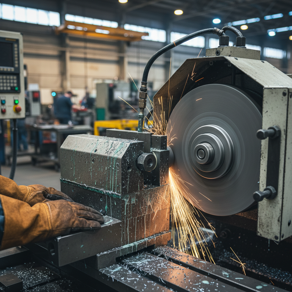
Precision grinding of titanium alloys (such as Ti-6Al-4V, Grade 5, and various beta-phase formulations) represents one of the most challenging frontiers in modern aerospace, medical device, and military manufacturing. While titanium offers an exceptional strength-to-weight ratio, outstanding corrosion resistance, and biocompatibility, its physical and thermal properties make it notoriously difficult to machine. Among the most persistent quality control failures encountered during cylindrical, surface, and creep-feed grinding of titanium are grinding taper issues.
In high-precision components—such as aircraft landing gear cylinders, turbine rotor shafts, and orthopedic joint implants—even a microscopic taper deviation across the workpiece length can lead to immediate scrap, compromised fatigue life, or catastrophic assembly failures. This comprehensive titanium grinding guide explores the mechanical and thermal root causes of taper errors, details the physics of titanium thermal bowing, and explains how advanced open-structure grinding wheel technology acts as the ultimate process-level solution to achieve zero-taper precision.
The Physics of Taper Formation in Titanium Grinding
To eliminate taper issues, we must first dissect the physical mechanisms that produce them. Unlike structural steels or nickel-based superalloys, titanium behaves in a highly unique manner under the mechanical and thermal stresses of the grinding arc. Taper issues are fundamentally caused by two interacting phenomena: mechanical deflection (due to low elastic modulus) and thermal distortion (due to extremely low thermal conductivity).
1. Mechanical Deflection and Low Elastic Modulus
Titanium alloys possess a relatively low modulus of elasticity (Young’s Modulus, $E$). For instance, Ti-6Al-4V has an elastic modulus of approximately 110 to 114 GPa, which is roughly half that of structural steels (typically 210 GPa).
During the grinding process, the normal force ($F_n$) exerted by the grinding wheel acts directly on the workpiece. Because the workpiece is elastic, it deflects away from the grinding wheel under this load. The magnitude of deflection ($w$) for a cylindrical workpiece supported between centers can be modeled using classical beam deflection equations:
$$w = \frac{F_n \cdot L^3}{48 \cdot E \cdot I}$$
Where:
- $F_n$ is the normal grinding force.
- $L$ is the unsupported length of the workpiece.
- $E$ is the Young’s Modulus of the material.
- $I$ is the area moment of inertia of the workpiece cross-section.
Because titanium’s $E$ value is so low, the workpiece deflects twice as much as a steel part of identical geometry under the exact same normal force. As the grinding wheel traverses along the workpiece, the stiffness of the setup varies: it is highly rigid near the chuck or tailstock and highly compliant (flexible) at the midpoint. This variable deflection directly manifests as a dimensional taper or “barrel” shape, where the center of the shaft remains oversized compared to the supported ends.
2. Titanium Thermal Bowing and Low Thermal Conductivity
The second, and often more severe, driver of taper errors is titanium thermal bowing. Titanium has an exceptionally low thermal conductivity ($k \approx 6.7 \text{ W/m}\cdot\text{K}$ for pure titanium, and $k \approx 5.8 \text{ to } 7.3 \text{ W/m}\cdot\text{K}$ for Ti-6Al-4V at room temperature). For comparison, mild steel has a thermal conductivity of approximately $50 \text{ W/m}\cdot\text{K}$, and aluminum exceeds $200 \text{ W/m}\cdot\text{K}$.
During grinding, a massive amount of friction is generated in the grinding zone. In steel grinding, a significant portion of this thermal energy is conducted rapidly into the bulk of the workpiece or carried away by the metal chips. In titanium grinding, however, the low thermal conductivity acts as a thermal barrier. The heat cannot escape into the bulk material quickly enough, resulting in an extreme, localized temperature spike at the grinding zone (often exceeding $1000^\circ\text{C}$ if unmanaged).
This localized heat causes rapid thermal expansion of the surface layer directly in contact with the wheel. Because only one side of the workpiece is heated and expanding while the opposite side remains cool, the workpiece undergoes asymmetric thermal expansion. This causes the workpiece to bend or “bow” toward the grinding wheel. As the part bows toward the wheel, the actual depth of cut increases, which in turn increases the grinding force and generates even more heat—a catastrophic thermal run-away loop. This thermal bowing dynamic causes severe dimensional instability and progressive taper errors along the traverse path.
How Wheel Loading and Glazing Amplify Taper Errors
The chemical properties of titanium further complicate the grinding system. Titanium is highly chemically reactive at elevated temperatures. When the grinding zone temperature rises, titanium exhibits a strong chemical affinity for most conventional abrasive grains (such as aluminum oxide). This leads to rapid chemical bonding and mechanical adhesion between the titanium chips and the abrasive crystals—a phenomenon known as wheel loading.
Additionally, if the grinding wheel bond is too hard or the abrasive is inappropriate, the abrasive grains will dull (flatten) without fracturing or releasing. This is known as wheel glazing. For a deeper look at diagnosing these surface defects, refer to our guide on Troubleshooting Grinding Burns: Fixing Glazing with Open-Structure Grinding Wheels.
When a grinding wheel suffers from loading and glazing:
- The sharp cutting edges of the abrasive grains are replaced by loaded titanium metal or flattened, dull grains.
- The cutting action of the wheel transitions from efficient “shearing/plowing” to highly inefficient “rubbing/sliding.”
- The normal grinding force ($F_n$) skyrockets.
- The Specific Grinding Energy (SGE) increases exponentially, dumping massive heat into the workpiece.
As the wheel traverses across the part, it becomes progressively more loaded and glazed. Consequently, the grinding forces and thermal inputs are not constant; they increase continuously from the start of the traverse to the end. The workpiece deflects and bows progressively more as the grind continues, resulting in a severe linear taper across the length of the workpiece.
The Open-Structure Grinding Wheel: Engineering the Solution
To eliminate taper issues, we must break the cycle of high grinding forces, wheel loading, and localized thermal expansion. The most effective weapon in a manufacturing engineer’s arsenal is the open-structure grinding wheel (also referred to as highly porous or induced-pore wheels).
Standard grinding wheels consist of three primary elements: abrasive grains, the bonding matrix (vitrified, resinoid, or metal), and natural pore spaces. In standard wheels, the pore space is highly compressed to maximize wheel density and form-holding capability. In contrast, an open-structure wheel is engineered with highly controlled, interconnected, and oversized pore networks, often achieved through the addition of specialized pore-inducing agents (such as naphthalene, organic beads, or highly engineered bubble alumina) during the manufacturing process.

1. Micro-Pocket Chip Clearance (Preventing Loading)
In an open-structure wheel, the massive, interconnected pores act as built-in micro-pockets. As the abrasive grains shear the titanium, the resulting long, ductile titanium chips are immediately channeled into these pore pockets. The chips are safely stored within the wheel’s structure during the brief duration of the grinding arc, preventing them from being forced into the wheel face and causing loading. Once the wheel rotates out of the grinding arc, centrifugal force and high-pressure coolant jets easily flush the chips out of the open pores, keeping the wheel face clean, sharp, and free of metal adhesion.
2. Maximized Coolant Transport and Air Barrier Penetration
At high peripheral speeds, grinding wheels generate a high-pressure boundary layer of air (an aerodynamic barrier) around their circumference. This air barrier acts as a shield, deflecting conventional coolant streams away from the grinding zone and causing “coolant starvation.”
Open-structure wheels solve this issue fundamentally. The highly porous, uneven surface of the wheel breaks up the boundary layer. More importantly, the interconnected pores act as a high-capacity “sponge” or ” sponge,” absorbing high-velocity coolant at the entrance of the grinding zone and releasing it directly into the cutting arc under intense centrifugal pressure. This continuous, pressurized delivery of coolant directly to the point of contact prevents the localized thermal spikes that drive asymmetric thermal expansion.
Furthermore, because the open pores disrupt the high-pressure boundary layer of air surrounding the fast-spinning wheel, they prevent the “dry grinding” phenomenon often caused by coolant starvation. To understand the dynamics of managing this boundary layer in high-speed applications, refer to our detailed analysis on Solving Coolant Starvation in High-Speed Grinding: Open-Structure Wheels and Baffles.
3. Lowering Specific Grinding Energy (SGE) and Normal Forces
Specific Grinding Energy (SGE, denoted as $e_c$) is the energy required to remove a unit volume of material. It is a direct indicator of the efficiency of the grinding process and is mathematically expressed as:
$$e_c = \frac{F_t \cdot v_s}{v_w \cdot a_e \cdot b}$$
Where:
- $F_t$ is the tangential grinding force.
- $v_s$ is the peripheral wheel speed.
- $v_w$ is the workpiece speed.
- $a_e$ is the depth of cut (infeed).
- $b$ is the grinding width.
When grinding titanium with a standard dense wheel, $e_c$ escalates rapidly due to loading and glazing, which increase friction (tangential force, $F_t$). In contrast, an open-structure wheel maintains highly efficient micro-cutting. Because the abrasive grains remain clean and sharp, the ratio of cutting-to-plowing is maximized. This drop in friction dramatically lowers both $F_t$ and $F_n$ (normal force).
By keeping the normal force ($F_n$) low and consistent across the entire traverse length, the mechanical deflection of the flexible titanium workpiece is minimized. For a comprehensive breakdown of how to control these forces, see our technical guide on Optimizing Specific Grinding Energy: Using Open-Structure Wheels to Balance Force Ratios.
Selecting the Right Open-Structure Wheel Specifications for Titanium
Eliminating taper requires selecting a wheel with the perfect synergy of abrasive type, grit size, bond grade, and induced porosity. The table below outlines the core differences between a standard wheel setup and an optimized open-structure wheel designed specifically for high-precision titanium grinding.
| Specification Parameter | Standard Grinding Wheel (Prone to Taper) | Zhongxin Open-Structure Wheel (Zero-Taper) |
|---|---|---|
| Abrasive Mineral | Standard Pink/White Aluminum Oxide (WA) | Highly Friable Ceramic Alumina (SG) or Green Silicon Carbide (GC) |
| Grit Size | 46 – 60 (Medium) | 80 – 120 (Fine, yet highly porous for finish and low force) |
| Grade (Hardness) | K to M (Medium-Hard) | F to H (Soft, promoting rapid self-sharpening) |
| Structure Number | 5 – 8 (Dense to Medium) | 12 – 18 (Induced Ultra-Open Porosity) |
| Bond Matrix | Standard Vitrified | High-Strength, Low-Temperature Vitrified (V) |
| Coolant Permeability | Low (< 15% pore volume) | High (> 48% interconnected pore volume) |
Using a soft bond grade (such as G or H) in an open-structure wheel ensures that as soon as an abrasive grain experiences slight dulling, the micro-forces cause it to fracture (micro-fracturing) or tear out of the bond matrix, exposing fresh, sharp cutting points. This self-sharpening mechanism keeps the grinding force constant from the beginning of the traverse to the end, preventing progressive taper formation.
Process Parameter Optimization for Zero-Taper Grinding
While installing an open-structure wheel is the most critical step, the grinding machine parameters must be tuned to leverage the wheel’s physical advantages. Below are the recommended parameters for cylindrical and surface grinding of Ti-6Al-4V alloys:
1. Wheel Speed ($v_s$) and Work Speed ($v_w$) Control
Keep the peripheral wheel speed ($v_s$) moderate—ideally between 20 m/s and 30 m/s. Excessively high wheel speeds increase the thermal energy generated per second, accelerating chemical reaction rates and wheel loading. Conversely, keep the work speed ($v_w$) relatively high ( 15 to 25 m/min) to minimize the contact time of any single point on the workpiece with the grinding zone. A higher work speed distributes the thermal energy over a larger surface area per unit of time, preventing localized heat accumulation and drastically reducing the amplitude of thermal bowing.
2. Depth of Cut ($a_e$) and Feed Rate Strategies
To prevent both mechanical deflection and thermal runaway, the depth of cut ($a_e$) should be carefully managed. Instead of deep, heavy cuts that generate high normal forces, engineers should employ a multi-step grinding strategy:
- Roughing Passes: Maintain a depth of cut between 0.015 mm and 0.030 mm per pass. This leverages the high chip-carrying capacity of the open-structure wheel without overloading the low-elastic-modulus titanium workpiece.
- Finishing Passes: Reduce the depth of cut to 0.005 mm to 0.010 mm. This reduces normal forces to near-zero, allowing the workpiece to return to its natural, undeflected state and correcting any minor dimensional errors introduced during roughing.
- Spark-out Passes: Perform 2 to 4 spark-out passes (zero-infeed passes) at the end of the cycle. Because the open-structure wheel does not load or glaze, these spark-out passes will cleanly shear off any microscopic high spots caused by residual elastic deflection, ensuring a perfectly straight, cylindrical profile.
3. Dressing Parameters: Maintaining the Open Structure
Even the best open-structure wheel will perform poorly if dressed incorrectly. The goal of dressing an open-structure wheel is to expose the engineered pore network rather than crushing it.
Use a sharp single-point or multi-point diamond dresser. A coarse dressing lead (traverse rate) is highly recommended. For example, a lead rate of 0.15 to 0.25 mm/rev with a relatively shallow dressing depth (0.01 to 0.02 mm) ensures that the wheel face remains highly open, sharp, and free of crushed bond debris. Fine dressing must be avoided, as it dulls the abrasive grains and closes up the vital surface pores, immediately re-introducing the risk of taper-producing thermal spikes.
4. Coolant Chemistry and Velocity Matching
Coolant delivery must be optimized to match the capabilities of the open-pore wheel. We recommend a high-quality, water-soluble synthetic or semi-synthetic fluid with highly active extreme-pressure (EP) additives (such as esters or phosphorus compounds) to minimize friction.
The coolant nozzle must be designed to match the peripheral speed of the wheel ($v_s$). If the coolant velocity is slower than the wheel speed, the aerodynamic boundary layer will deflect the fluid. By matching the coolant jet velocity to the wheel speed, the fluid penetrates the boundary layer and is absorbed directly into the open pore network, which then carries it directly into the grinding contact zone.
Conclusion: Achieving Zero-Taper Precision in Titanium Grinding
Overcoming the inherent challenges of titanium grinding—specifically the material’s low thermal conductivity and high chemical reactivity—demands a highly engineered approach to wheel selection. Standard abrasive configurations inevitably lead to localized heat accumulation, causing thermal expansion of the workpiece and resulting in unacceptable taper errors. By implementing open-structure, highly porous vitrified bond wheels, manufacturers can dramatically improve coolant delivery directly to the grinding zone, reduce friction, and facilitate efficient chip clearance. This specialized design minimizes grinding forces and thermal deflection, ensuring exceptional dimensional stability, surface integrity, and the realization of true zero-taper precision in demanding aerospace and medical applications.
Partner with Zhengzhou Zhongxin for High-Precision Grinding Solutions
At Zhengzhou Zhongxin Grinding Wheel Co., Ltd., we specialize in engineering high-performance, customized grinding solutions tailored to the rigorous demands of titanium and exotic alloy processing. Whether you require bespoke open-structure wheel formulations to eliminate taper issues or seek to optimize your high-volume production efficiency, our technical team is ready to assist you. Contact us today to discuss your specific application requirements, request a technical consultation, or receive a competitive quote.
Zhengzhou Zhongxin Grinding Wheel Co., Ltd.
Phone/WhatsApp: +86 15538050608
Email: root@shalun.net
Address: No. 1111-1, Kexue Avenue, Shangjie District, Zhengzhou, Henan, China.

© 2026 Zhengzhou Zhongxin Grinding Wheel. All Rights Reserved.